Application with Engineering Technology & Tools
Here are projects I've completed throughout my engineering program that have involved a variety of tools and technologies, including CAD software, VEX Robotics, and various power tools. These projects have allowed me to apply engineering principles in practical ways, demonstrating my proficiency with these tools and my ability to solve complex problems through design and iteration.
CAD with SolidWorks
Throughout my engineering work, I have demonstrated advanced proficiency in Computer-Aided Design (CAD), primarily utilizing SolidWorks for modeling objects. I also explored alternatives such as TinkerCAD for simpler concepts. Proficiency in CAD has further developed my skills in technical drawings, including the creation of orthographic projections, enabling effective communication of designs between teams.
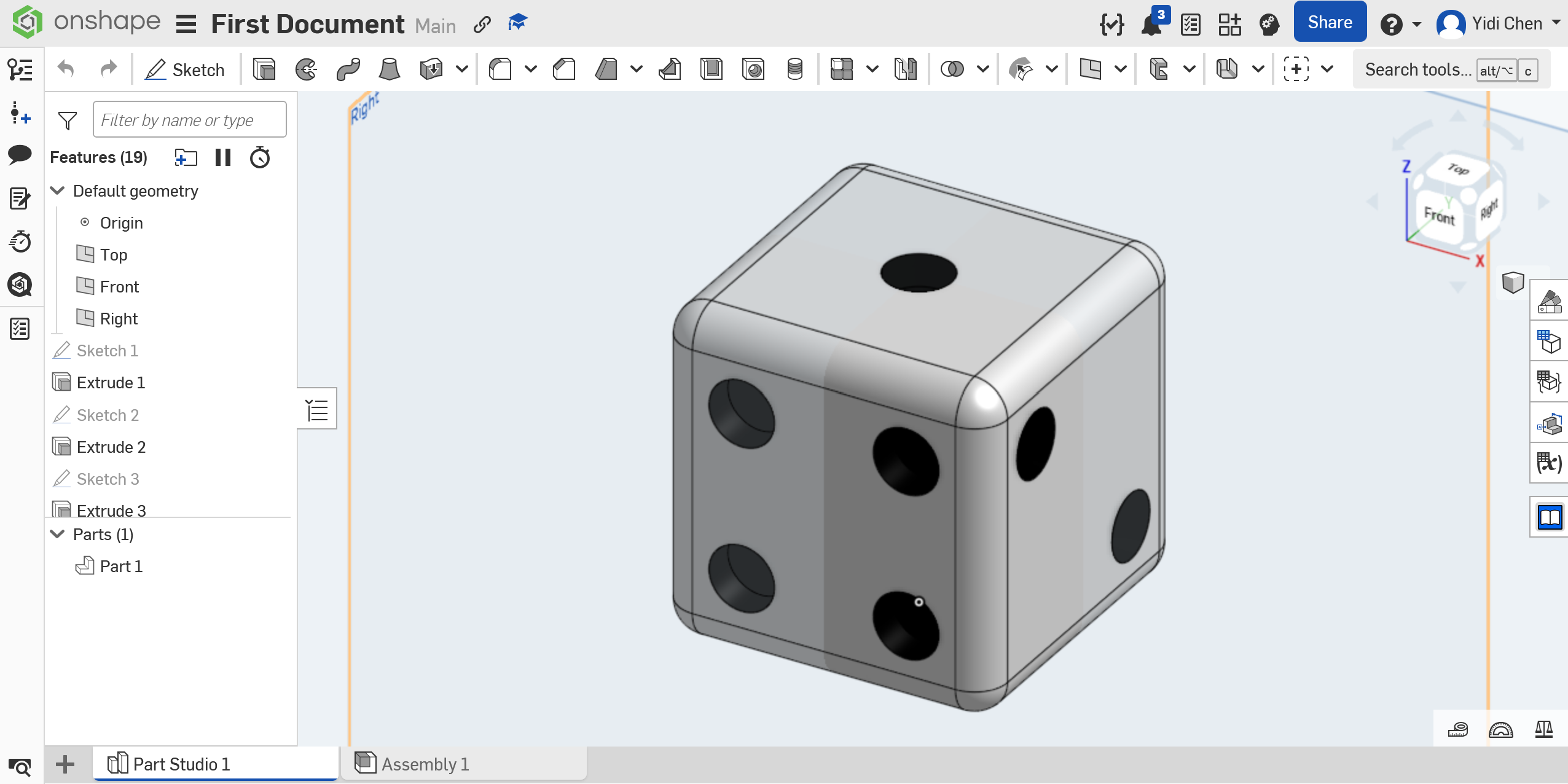
My initial application of SolidWorks occurred during the dice construction project, where I created a fully defined 3D part model of a standard six-sided die. This involved employing specific modeling techniques, including extruded bosses for the base cube, fillet and chamfer operations to refine the edges, and using "Extruded Cut" to create cylindrical holes.
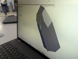
Subsequently, during the cardboard boat design challenge, I furthered my CAD expertise by developing detailed multi-body part models and assemblies of scaled boat prototypes. These models used angled surfaces and the shell tool to shape the boat's hull for better buoyancy and smoother traveling through water. We exported the final designs as OBJ files, which worked well with 3D printers for rapid prototyping. This let my team quickly print and test several versions, checking how well they floated and handled water displacement.
These projects showed strong use of SolidWorks features. Looking back, combining CAD modeling with 3D printing made the engineering design process much faster and easier, helping us refine ideas and finish projects more efficiently.
VEX Robotics
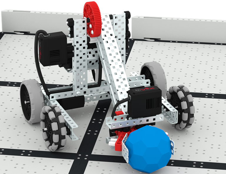
During my first year in the engineering program, I worked on a VEX Robotics project, completing foundational tutorials to gain in-depth knowledge of robotic components and their functions. I also utilized VEX's block-based programming to manipulate robot operations effectively. Building on these skills, my team designed and constructed a robot for intaking and scoring game objects in a competitive field.
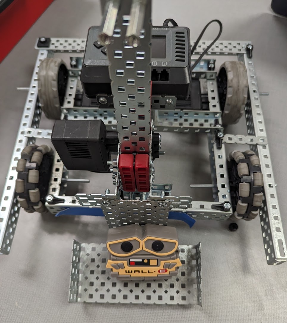
Following the engineering design process, we brainstormed designs, focusing on mobility and stability, then assembled a drivetrain using VEX C-channels, motors, and omni-wheels for versatile navigation. For manipulation, we integrated a vertical elevator system with linear sides, powered by V5 Smart motors and geared for controlled ascent and descent. At the base of the elevator, we attached a forklift-style scoop mechanism to intake objects from the field and secure them during elevation for scoring. My programming mapped controller inputs to drivetrain and elevator control, with iterative testing to optimize stability.
This demonstrated advanced proficiency in VEX tools and software, integrating principles of torque, mechanical advantage, and structural integrity. It highlighted the importance of improvement by trials of testing.
Dice Project using Chop Saw, Belt Sander, Router, & Drill Press
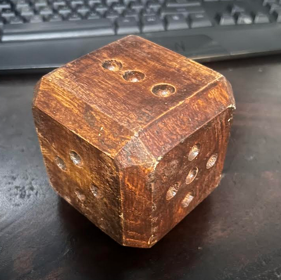
In the program's Wooden Dice project, we started with a longer rectangular block of wood and progressively machined it into a six-sided die using stationary power tools. This step-by-step process emphasized safety, precision, and proper technique with each tool.
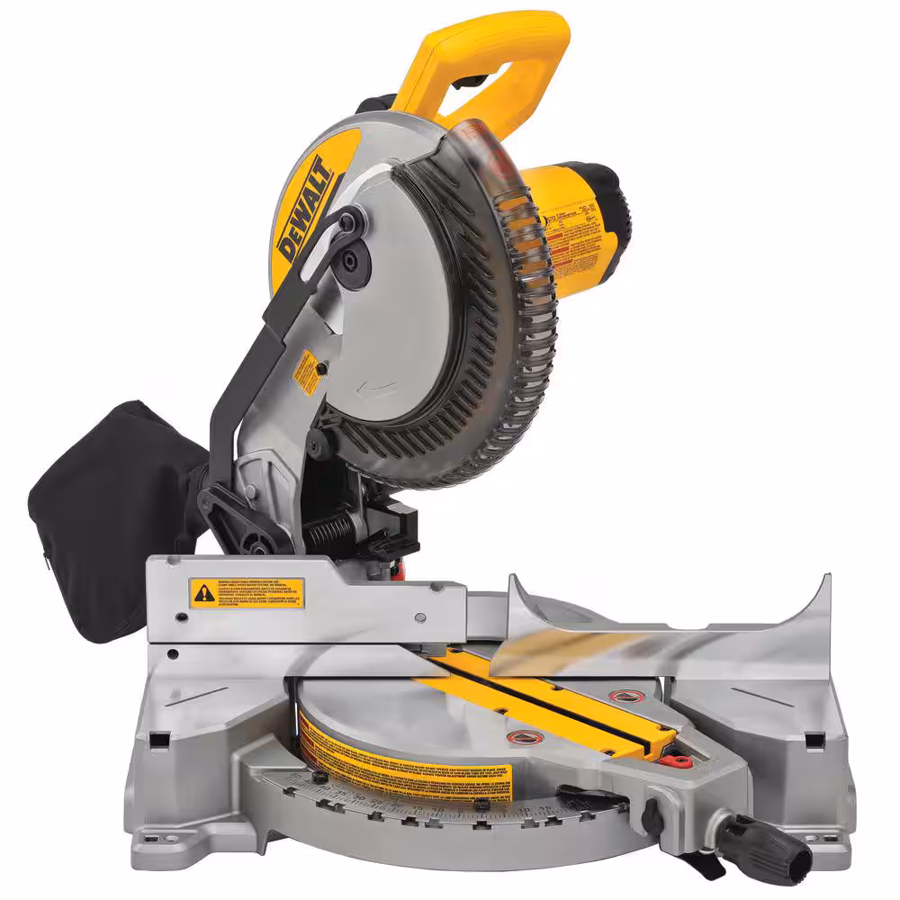
Step 1: Rough Cutting to Cube Shape
After becoming certified on the chop saw, I used it to cross-cut the longer wood stock into a rough cube. By aligning the wood firmly against the fence and making controlled, slow cuts, I ensured clean, perpendicular ends and avoided tear out or kickback, crucial for starting with accurate dimensions.
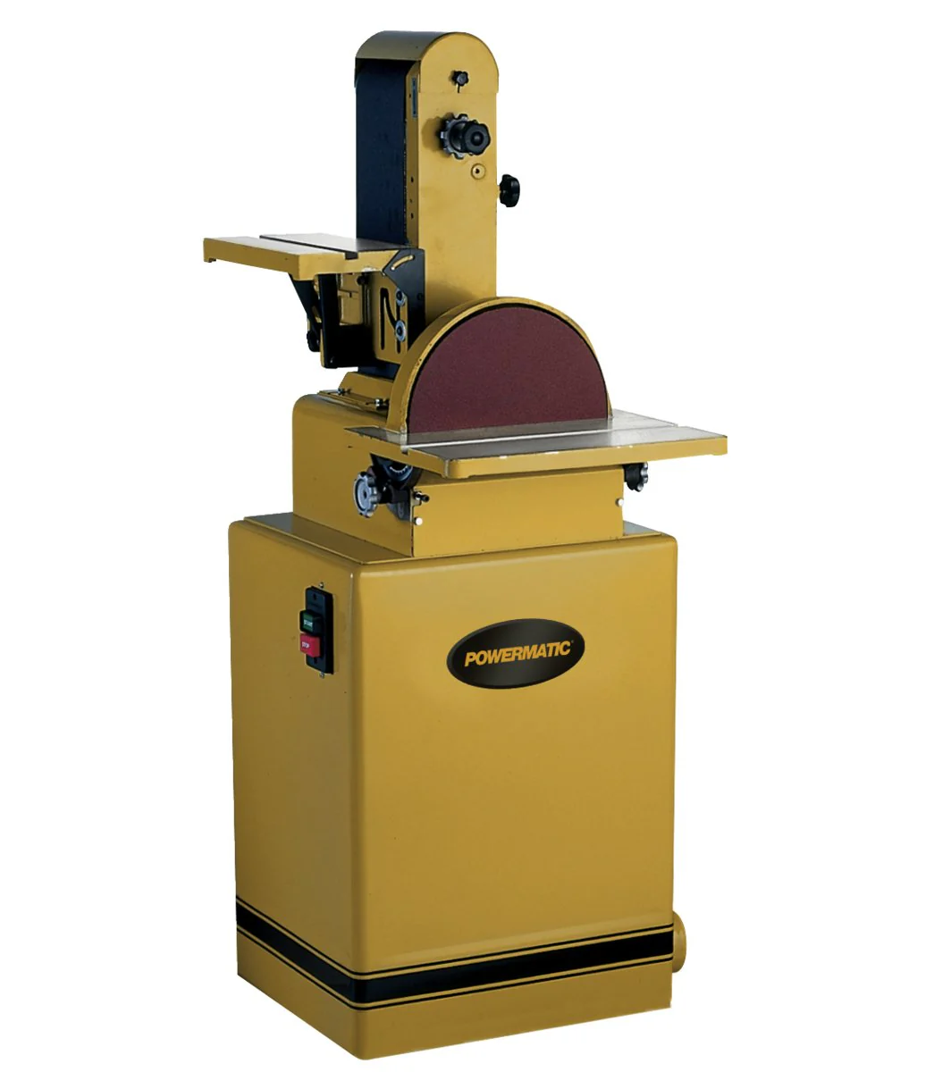
Step 2: Smoothing and Flattening Faces
Then, I operated the belt sander to smoothen all six faces of the cube. Starting with coarser belts and progressing to finer ones, I applied even pressure and moved with the grain to achieve flat, parallel, and smooth surfaces essential for a balanced rolling die.
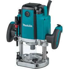
Step 3: Chamfering the Edges of the Dice
To create safe, rounded corners and edges, I used the router equipped with a chamfer bit. I applied uniform passes along all 12 edges of the die to produce consistent bevels without burning or chattering the wood.
Step 4: Drill the Pips (Dots)
I marked the specific spots where dots should be centered on each side of the die. Finally, on the drill press, I bored the respective markings for numbers 1 through 6 using a Forstner bit for flat-bottomed, clean holes.
Step 5: Finishing & Reflection
This project finished with applying a clear wood coating to protect the die. Despite the protective coating, after dozens of rolls during testing, the die exhibited chipping and edge damage on corners. This process showed how proper tool use affects the final quality: the chop saw ensured square cuts to start right, the belt sander required patience to avoid gouges and get smooth faces, the router needed steady hands for even chamfers, and the drill press created precise holes.