Application of Scientific Laws and Principles Competency
Introduction
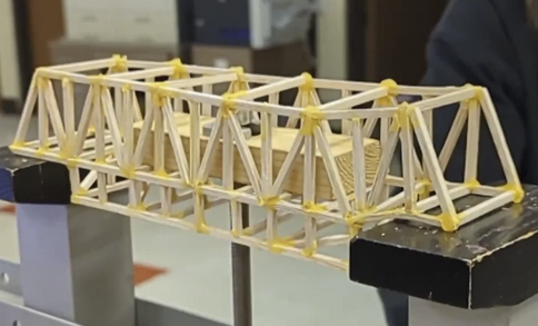
During my program, we were introduced to the world of bridges and the outstanding designs that utilize physics and forces. This project required designing and constructing a balsa wood bridge capable of sustaining over one hundred pounds of load. Working with a partner, the project taught us a working understanding of structural mechanics, specifically the principles of tension and compression, and how these forces vary through different bridge designs.
Scientific Principles
The two governing principles I utilized and learned throughout this project were tension and compression. Compression is a pushing force, meaning members under compression are being squeezed along their length. Tension is the exact opposite, a pulling force where members are being stretched. In a bridge under load, these forces are always present simultaneously, and the key engineering challenge is designing members and joints that can handle whichever force they will experience without buckling or fracturing.
Our research showed that balsa wood behaves differently under each force. While it handles compression reasonably well, its lightweight, porous core makes it much more vulnerable to tension and lateral stress. This meant that joint placement and member orientation had to be deliberate decisions rather than aesthetic ones, since a poorly aligned joint in a high-tension region could cause the bridge to fail well below the target load. This proved to be right when we moved on to simulating our bridge prototypes.
Simulation and Design Selection
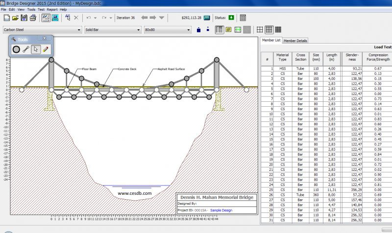
Before any physical construction, we used West Point Bridge Designer to model and simulate different bridge configurations. The software allowed us to visualize how forces distributed through each member under a given load, showing which members were in tension, which were in compression, and by how much. We tested truss, beam, and suspension configurations and compared how each handled the load distribution.
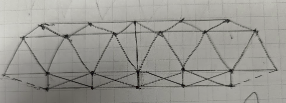
The truss design performed best across our simulations. A truss works by converting applied loads into axial forces along its members, spreading the load more evenly than a simple beam would. By triangulating the structure, each member carries primarily either tension or compression rather than bending, which is structurally much more efficient and reduces the risk of failure at any single point.
Material Planning
Before cutting any balsa, we calculated exactly how much material the truss design would require. Summing the lengths of every planned member across the full truss gave a total of 176.4375 inches of balsa wood needed. From there the math was straightforward:
Total member length = 176.4375 in
Each balsa stick = 12 in
176.4375 ÷ 12 = 14.703 sticks (total linear material)
14.703 ÷ 2 = 7.35 sticks per side (symmetric two-truss structure)
Round up → 8 sticks
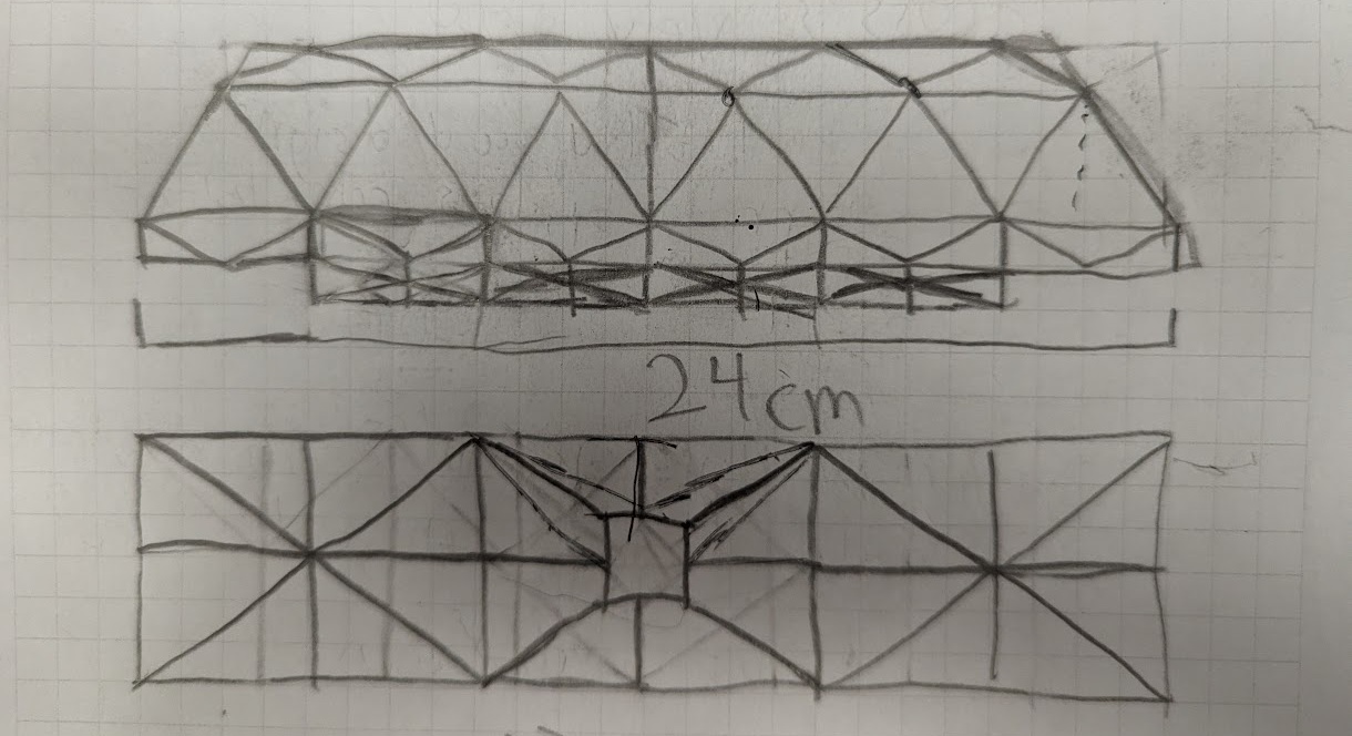
Because the bridge is symmetric, both side trusses are identical, so the total linear length is split evenly between them. Rounding 7.35 up to 8 ensured we had enough material without mid-build shortages that could have forced last-minute design compromises. This pre-construction calculation is a direct product of choosing the truss configuration: a simpler beam design with fewer members would have required less planning, but the truss's triangulated geometry and greater member count made quantifying materials upfront essential.
Construction and Iteration
With the simulation results and material plan in hand, we built the bridge using the truss configuration that had shown the most balanced force distribution. The simulation data guided specific decisions like the angle and distances between each joint, and how long each member should be when sized down to our bridge scale, since we could anticipate which members would carry the greatest load and reinforce accordingly.
Testing and Results
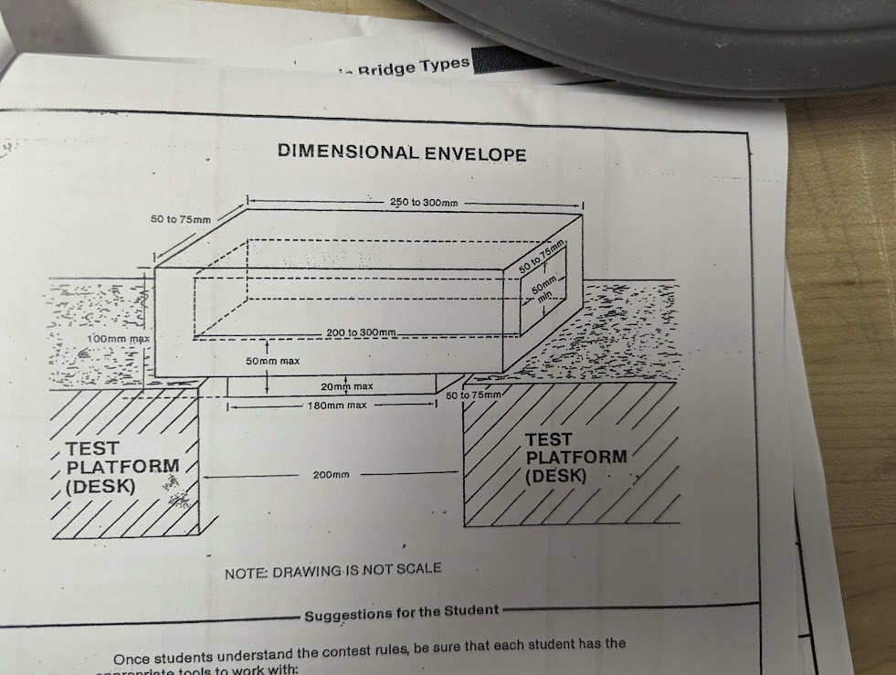
During load testing, a key constraint emerged: the bridge's deck width was not wide enough to accommodate the standard testing block. We were required to switch to a smaller block, which significantly reduced the contact surface area between the block and the bridge.
This matters because of a fundamental relationship in physics: pressure is defined as force divided by area, or P = F / A. When the applied force stays the same but the surface area decreases, the pressure at the contact point increases proportionally. In practical terms, switching to the smaller block concentrated the same load into a much smaller footprint on the bridge deck, increasing the stress at that point and making failure more likely at a lower total load than the simulation predicted. It is a direct consequence of one of the most basic scientific principles in structural engineering, and a reminder that real-world geometric constraints can undermine an otherwise sound design.
Why Scientific Principles Matter
Understanding tension and compression was not just academic background knowledge. It was directly what made informed design decisions possible. Without knowing how forces move through a structure, designing a bridge becomes guesswork, and the margin for catastrophic failure increases substantially. In a real engineering context, structures like bridges, buildings, and frames are designed with these exact principles as the foundation. Ignoring or misapplying them is how real structures fail. This project demonstrated on a smaller scale exactly why scientific laws and principles are not optional considerations in engineering, but the basis from which every design decision should follow.